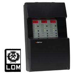
Detnov Carbon Monoxide Detectors
Electrochemical cell technology for high-quality and safe measurement
Detection and response time below 10 seconds
Two-wire polarity-free connection infrastructure
IP21 and IP54 protection class options
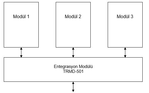
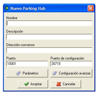
TRMD-501 Ethernet Output, Frequency Converter Driver Output Board
TRMD-501 is an energy-efficient Modbus interface board to which up to three
variable-speed drives can be connected, controlling three motors and ensuring that exhaust (extraction) fans
operate with optimum performance. TRMD-501 is designed to minimize energy consumption in systems and to reduce
noise levels in ventilation units. Through SCADA software integration, the board enables remote
control and monitoring of the system. It is an RS-485 / ETHERNET Modbus module used to integrate
the CO system into SCADA and other supervisory software platforms.
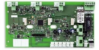 TRMD-501 Modbus Communication and Frequency Converter Driver Board
 (integrated into the CO panel)
Objectives
The purpose of this document is to explain the
integration functions and
operating principles of the carbon monoxide detection system.
Introduction
The
carbon monoxide system measures the CO concentration in a defined protection area. When the
concentration reaches a certain threshold, the system automatically activates the relevant ventilation groups via
panel outputs or through software integration over
SCADA. This reduces CO concentration below the
pre-defined safety levels. The system performs ventilation control both
in software and in hardware.
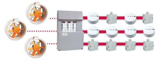
The system consists of the following components:
-
Zone modules: Integrated into the carbon monoxide panel. Zone modules act as a user interface,
collecting CO concentration values from detectors and displaying them on the panel. Up to
32 CO detectors can be connected to each zone module and the CO sensors are controlled via the
module. The module contains all control elements that provide functionality to the system.
Up to 3 zone modules, totalling 96 CO detectors, can be connected to a single CO panel.
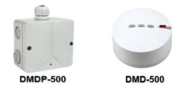
-
CO detectors: Responsible for measuring the CO concentration in the protection
area. They are continuously queried by the zone module to obtain CO concentration values.
-
Integration card: An RS-485 / ETHERNET Modbus module used to integrate the CO
system with SCADA and other supervisory software.
Each card has the capacity to fully manage three zone modules, i.e., one panel. The card can control
variable-speed drives in order to minimize the energy consumption of exhaust fan groups.
From an integration perspective, there are two system types:
-
Conventional: The protection area is divided into zones. Each zone has several CO detectors
that measure the concentration in that area. This type of system only displays the maximum or average
CO concentration value of the protected area. Activations are made according to one of these parameters.
-
Analog: This system is very similar to analog fire detection systems. It allows
monitoring of the CO concentration at each point and executing actions accordingly. Since much more
information is available compared to a conventional system, the system can be operated much more efficiently.
Both systems are based on the same hardware platform; the physical components used to build a conventional or
analog system are identical. The user can configure the system as a conventional or analog CO
detection system.
-
Conventional System: The user does not assign addresses to the detectors; the panel assigns
them automatically. In this case, the physical location of the detector in the field cannot be uniquely
associated with the address assigned by the control module.
-
Analog System: The user can assign addresses to detectors. In this case, the location of the
detector in the installation is linked to the address assigned. In SCADA integration, it is
possible to create zoning on SCADA independently from the cabling. Through the TRMD-501 Modbus card,
the information of each detector is transferred to SCADA, jet fans and other systems, and the desired zone maps
are defined in these systems. Ventilation control via SCADA, jet fans, etc. can be carried out based on these
zone maps.
Zone Control Modules
A carbon monoxide panel supports up to
three zone modules and a total of
96 CO detectors. For
SCADA and jet fan integration, the
TRMD-501 communication card is used, which acts as a hub for the system.
External
MODBUS requests are sent to the integration module, which then distributes them to the
relevant zone module. Requests are transmitted using the
MODBUS/RTU protocol over
RS-485 and/or UDP/IP connections.
Use of the Conventional System
In conventional CO detection systems, up to 32 CO detectors can be connected to each zone module
on the panel. A total of 96 detectors can be connected to a single CO panel.
In this type of system, it is sufficient for the installer to mount the detectors in the field and energize the
equipment.
The panel assigns addresses to all devices on the bus and then starts collecting CO concentration data. Decisions
to activate ventilation groups via the module can be based on the following parameters:
- Maximum concentration of the detector group
- Average concentration of the detector group
The information available for SCADA is as follows:
- Number of detectors
- CO concentration value of each detector
- Temperature value of each detector
- Operation mode
- Zone module contact status
Analog System
In this case, the system topology is the same, but each detector is assigned an address that defines its location
in the installation.
The operation principle is the same as in the previous case; decisions can be made based on the maximum value or
the average concentration value.
The information available for SCADA is the same as in the conventional system; however, since each detector can
be addressed individually, the user can define zoning in software with flexible configurations.
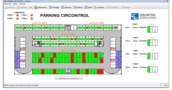
It is possible to perform zoning on SCADA independently of the cabling. Through the
TRMD-501 Modbus card, information about each detector is transferred to SCADA, jet fans and similar systems, and
the desired zone maps are defined there. Car park ventilation control via SCADA, jet fans, etc.
can then be performed according to these zone maps.
The information available for SCADA is as follows:
- Number of detectors
- Concentration value of each detector
- Temperature value of each detector
- Operation mode
- Zone module contact status
Integration
System integration is based on the MODBUS protocol. Each panel in the system can be monitored
and controlled remotely.
The information provided by each zone module on the panel is:
- Module serial number
- Status of outputs
- Operation mode
-
Internal module information:
a. Decision thresholds
b. Number of alarms
c. Number of faults
d. Partial counter for alarms and faults
e. Number of conventional detectors
f. Number of analog detectors
-
Internal detector information:
a. Detector type indicator: - No detector - Conventional detector - Analog detector
b. Detector status: - Instant Measurement - Alarm - Fault
c. Concentration value
d. Temperature value
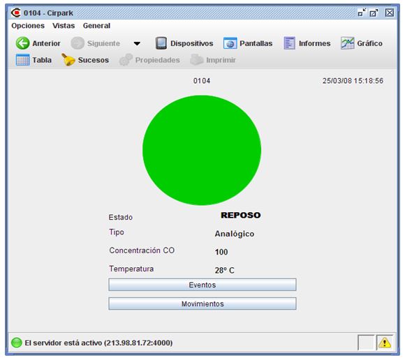
The carbon monoxide panel automatically detects detectors and the software displays them on the screen.
Detectors can be distinguished as analog or conventional so that they can be added to the SCADA
map and used to retrieve information for visualization.
On the SCADA side, it is possible to monitor both the carbon monoxide panel and all connected
detectors, as well as the status of communication card outputs.
For each detector, all information can be visualized in detail on monitoring screens.
Sensors or detectors can always be added to a SCADA screen; it is possible to access all variables of both the
sensors and the control unit.
System Map
The memory map of the carbon monoxide panel is distributed as follows:
- 1. Serial number
-
2. General installation information:
- a. Number of detectors in the system. This parameter is configured at system start-up and can be used to
determine whether any detector has been removed.
- b. Number of analog detectors
- c. Number of conventional detectors
- d. Alarm counter
- e. Fault counter
- f. Partial alarm and fault counter
-
3. General operating information:
- a. Maximum instantaneous CO concentration
- b. Instantaneous average CO concentration
- c. Instantaneous minimum CO concentration
- d. Maximum instantaneous temperature
- e. Instantaneous average temperature
- f. Instantaneous minimum temperature
- g. Status of any output
- h. Status of control outputs
- i. Status of alarm output
- j. General status of the panel
-
k. Alarm level:
- i. 25 ppm
- ii. 50 ppm
- iii. 75 ppm
- iv. 100 ppm
- v. 125 ppm
- vi. 150 ppm, etc.
-
l. Operation mode:
- vii. Out of service
- viii. Normal operation mode
- ix. Automatic operation based on maximum values
- x. Automatic operation based on average values
-
4. Detector information:
- a. Detector address
-
b. Detector type:
- i. No detector
- ii. Conventional operation mode
- iii. Analog operation mode
-
c. Detector status:
- iv. Normal / Standby
- vi. Alarm
- vii. No communication
- viii. Device sensor fault
- d. Detector CO value
- e. Detector temperature value
-
5. Performance logs:
-
a. Mode change log:
- ix. Out of service
- x. Operation mode
- xi. Automatic operation based on maximum values
- xii. Automatic operation based on average values
- b. Device test start log
-
c. Alarm threshold changes:
- xiii. 25 ppm
- xiv. 50 ppm
- xv. 75 ppm
- xvi. 100 ppm
- xvii. 125 ppm
- xviii. 150 ppm, etc.
-
6. Records related to PWM outputs for speed control:
- a. Current speed control value
The table of Modbus registers is as follows:
| Address |
Register |
Bytes |
Description |
W/R |
| 0x0000 |
2 |
4 |
Serial number |
R |
| 0x0002 |
1 |
2 |
Table version / Number of detectors |
R |
| 0x0003 |
1 |
2 |
Number of analog / Number of conventional detectors |
R |
| 0x0004 |
1 |
2 |
Alarm counter |
R |
| 0x0005 |
1 |
2 |
Fault counter |
R |
| 0x0006 |
1 |
2 |
Partial counter for alarms and faults |
R |
| 0x0007 |
1 |
2 |
Exhaust fan counter 1 |
R |
| 0x0008 |
1 |
2 |
Exhaust fan counter 2 |
R |
| 0x0009 |
1 |
2 |
Partial exhaust counter 1 and 2 |
R |
| 0x000A |
1 |
2 |
Maximum instantaneous CO |
R |
| 0x000B |
1 |
2 |
Instantaneous average CO |
R |
| 0x000C |
1 |
2 |
Instantaneous minimum CO |
R |
| 0x000D |
1 |
2 |
Maximum instantaneous °C / Average instantaneous °C |
R |
| 0x000E |
1 |
2 |
Instantaneous minimum °C |
R |
| 0x000F |
1 |
2 |
Alarm level |
R/W |
| 0x0010 |
1 |
2 |
Concentration level 2 |
R/W |
| 0x0011 |
1 |
2 |
Concentration level 1 |
R/W |
| 0x0012 |
1 |
2 |
Operation mode |
R/W |
| 0x0013 |
1 |
2 |
Status of CO control panel |
R |
| 0x0014 |
1 |
2 |
Battery status |
R |
| 0x0015 |
1 |
2 |
PWM speed |
R |
| 0x0016 |
|
|
Reserved |
R |
| 0x0015 |
1 |
2 |
Detector 1 address / Detector 1 type (8 bits) |
R |
| 0x0016 |
1 |
2 |
Detector 1 status (8 bits) / Detector 1 temperature (8 bits) |
R |
| 0x0017 |
1 |
2 |
Detector 1 concentration |
R |
| 0x0018 |
765 |
1530 |
Other elements |
R |
NOTE 1: PWM data may vary depending on the speed control device.
NOTE 2: Thanks to Modbus function 0x04, it is always possible to read multiple data items at the
same time. That is, the status of multiple devices can be read simultaneously. In particular, the status
information of all detectors can be read instantly in blocks of 128.
The accessible Modbus input / output table is as follows:
| Address |
Description |
W/R |
Format |
| 0X0000 |
Alarm output status |
R |
|
| 0X0001 |
Output_dos output status |
R |
|
| 0X0002 |
Output_one output status |
R |
|
| 0X0003 |
5 Reserved |
R |
|
| 0X0008 |
Reset partial alarm counters, faults, level 1 and level 2 |
W |
|
| 0X0009 |
Test start or Test |
R / W |
|
| 0X0010 |
Mute PBX |
W |
|
It is possible to change the Modbus device address of the control panel. To do this, the first
free address or manufacturer address allowed by Modbus function 0x64 (100) is used. This command
is sent as a broadcast using address 0x00, and only the device whose serial number matches the one in the command
responds. An example of this command is:
| Address |
Function |
Address |
Number of registers |
Number of bytes |
Serial number (5 bytes) |
New Modbus address (1 byte) |
CRC (2 bytes) |
| 0x00 |
0x64 |
0x00 0x00 |
0x03 |
0x00 0x06 |
0x00 0x80 0x09 0x01 0x08 |
0x01 |
0x95 0xD6 |
The structure follows a standard Modbus command frame, but adds a new function with code 0x64:
- The address is always 0x00 and indicates that the command is sent as a broadcast.
- The function is manufacturer-specific.
- The address field is currently fixed at 0x00 0x00. Other manufacturers can define their own functions in this field.
- In this case, the number of registers is 3.
- The number of bytes is 6, corresponding to three registers of 2 bytes each.
- The serial number is 5 bytes including the initial 0x00; the actual serial number is 4 bytes.
- The new Modbus address is 1 byte and must be between 0x01 and 0xFE.
- The last field is a two-byte CRC.
A possible response to this command is:
| Address |
Function |
Address |
Number of registers |
CRC (2 bytes) |
| 0x01 |
0x64 |
0x00 0x00 |
0x03 |
0x46 0xF1 |
Annex 1. Modbus Protocol
1 – Introduction
The Modbus protocol is an industrial communication standard that allows multiple computers and
devices to form a network. Modbus defines the communication format from commands to message frames. The Modbus
protocol has three different implementations: Modbus RTU, Modbus ASCII and
Modbus/TCP (RTU or ASCII).
A typical Modbus RTU message has the following format:
| Address |
Function |
Data |
CRC |
| 1 byte |
1 byte |
n bytes |
2 bytes |
2 – Error Codes
When an error occurs in Modbus, a response similar to the following is received:
| Address |
Error message |
CRC |
| 1 byte |
0x81 0x02 |
2 bytes |
The error message consists of two bytes; the first code corresponds to an AND operation between 0x80 and the
function code (if the function is 1 → 0x81, function 5 → 0x85, function 0x10 → 0x90, etc.), and the second byte is
a general identifier of the error type:
| Error type |
Name |
Description |
| 1 |
Function |
Function code not available |
| 2 |
Data address |
Data address is not correct or does not correspond to readable/writeable data |
| 3 |
Data value |
Data value is not valid |
| 4 |
Device error |
Device could not process the request |
| 5 |
ACK |
The device has accepted the request but cannot execute it at the moment. It should not be retried. |
| 6 |
Device busy |
The device is processing another request and cannot accept new ones. It should be retried. |
3 – Implemented Functions
The following Modbus protocol functions are implemented in the CO panel:
- Function 01 (0x01): Read coil status (compressed relays or inputs)
- Function 04 (0x04): Read registers
- Function 05 (0x05): Write single coil (relay write)
- Function 16 (0x10): Write multiple holding registers
4 – Modbus Examples
The following sections show frame examples for both read and write operations in the Modbus protocol.
In particular, reading/writing relays or inputs and reading/writing registers are covered.
Reading compressed relays or inputs
The Modbus request will be as follows:
| Address |
Function |
Address (2 bytes) |
Data (2 bytes) |
CRC (2 bytes) |
| 0x01 |
0x01 |
0x00 0x00 |
0x00 0x03 |
0x7C 0x0B |
In the device response, specific data are obtained for each input. The status is represented as 1 = ON and 0 = OFF.
| Address |
Function |
Number of bytes |
Data |
CRC |
| 0x01 |
0x01 |
0x01 |
0x03 |
0x90 0x48 |
This indicates that inputs 1 and 2 are active (0x03 corresponds to 00000011 in binary).
Writing a relay
The Modbus request will be as follows:
| Address |
Function |
Register (2 bytes) |
Write value (2 bytes) |
CRC (2 bytes) |
| 0x01 |
0x05 |
0x00 0x09 |
0xFF 0x00 |
0x5C 0x38 |
The value to be written depends on the desired state. To activate the output, write 0xFF00; to deactivate it, write 0x0000.
In the device response, the same frame that was sent is returned.
| Address |
Function |
Register (2 bytes) |
Write value (2 bytes) |
CRC (2 bytes) |
| 0x01 |
0x05 |
0x00 0x09 |
0xFF 0x00 |
0x5C 0x38 |
In this example, we activate register 9 (test start).
Reading registers
The Modbus request will be as follows:
| Address |
Function |
Register (2 bytes) |
Number of registers (2 bytes) |
CRC (2 bytes) |
| 0x01 |
0x04 |
0x00 0x04 |
0x00 0x01 |
0x70 0x0B |
Each register consists of two bytes, so in the device response we obtain twice the number of bytes as the number of registers requested.
| Address |
Function |
Number of bytes (1 byte) |
Data (N bytes) |
CRC (2 bytes) |
| 0x01 |
0x04 |
0x02 |
0x00 0x05 |
0x79 0x33 |
In this case, we can see that register 0x04 contains the value 0x00 0x05 (there are 5 alarms in the alarm log).
Writing registers
The Modbus request will be as follows:
| Address |
Function |
Register (2 bytes) |
Number of registers (2 bytes) |
Number of bytes (1 byte) |
Data |
CRC (2 bytes) |
| 0x01 |
0x10 |
0x00 0x0E |
0x00 0x01 |
0x02 |
0x00 0x64 |
0xA6 0x95 |
In the device response, we obtain the start address of the write request and the number of registers written.
| Address |
Function |
Register (2 bytes) |
Number of registers (2 bytes) |
CRC (2 bytes) |
| 0x01 |
0x10 |
0x00 0x0E |
0x00 0x01 |
0x60 0x0A |
In this example, a single register (2 bytes) with the value 0x00 0x64 is written to address 0x00 0x0E and the
correct response is obtained (we write a trigger level of 100 to register 0x00 0x0F).